What are the electrical requirements for a residential lift? This question deserves more than a simple voltage figure. A residential lift may need a dedicated power circuit, suitable isolation, effective earthing, overload protection, and reliable emergency systems. Exact requirements depend on the lift design, motor type, travel height, location, and local electrical rules. Safety comes first.
In a real installation, the electrician may inspect the main distribution board, cable route, breaker capacity, and available supply before work begins. The lift manufacturer should provide connection data, starting current, control-panel requirements, and standby-power specifications. A small machine-room lift can differ greatly from a compact machine-roomless model. Details matter. Emergency lighting, alarm communication, door interlocks, and battery lowering equipment also deserve close attention. These features are not decorative additions; they support safe passenger release during a power failure.
A careful guide must acknowledge uncertainty. Published specifications can change between models, and older homes may have limited electrical capacity. A checklist may look complete while missing local inspection requirements or voltage fluctuations. That is why a qualified electrician should verify the installation against the manufacturer’s instructions and applicable regulations. A lift supplier, building professional, and electrical inspector may each identify different risks. Their advice should align before energisation. Practical experience also matters: cramped cable spaces, damp basements, and long routes can affect performance. Some details remain easy to overlook. This article explains the main electrical considerations clearly, while recognising that final approval belongs to competent professionals familiar with the property and jurisdiction.
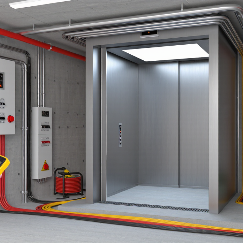
A residential lift needs a dedicated electrical supply, not a shared kitchen or garage circuit. The installer should confirm the lift’s rated voltage, full-load current, starting current, and standby demand. Many domestic systems use single-phase power, but the required rating varies by motor and travel height. The circuit should include overcurrent protection, a local isolator, and reliable earthing. NFPA 70, the National Electrical Code, places lift equipment within specific rules for disconnecting means and wiring methods. IEC 60364-5-52 and IEC 60364-5-54 also guide cable sizing and protective conductors.
Cable length matters. Voltage drop can cause failed starts, nuisance trips, or uneven operation. Keep it low. The circuit designer should calculate voltage drop under motor-start conditions, not only normal running load. Residual-current protection may be required by local rules, especially where equipment is exposed to moisture. A surge protective device can also help protect sensitive controls, although it is not a substitute for correct earthing.
NFPA research reported roughly 35,000 U.S. home fires annually involving electrical distribution and lighting equipment during 2012–2016, with about 470 deaths and 1,100 injuries. That data is not lift-specific, but it shows why shortcuts deserve scrutiny.
In practice, the final circuit should be tested after installation and again after commissioning. Record insulation resistance, earth continuity, polarity, protective-device operation, and emergency lowering performance. Some specifications overlook battery charging current. That can be a mistake. Requirements differ between jurisdictions, so a qualified electrician must verify the design against current local regulations and the lift manufacturer’s technical schedule.
A residential lift needs a carefully planned electrical system, not just a nearby socket. The control panel coordinates movement, door locks, sensors, and stopping accuracy. It should sit in a dry, accessible location with clear labels and enough working space. During servicing, technicians need to identify each circuit quickly. Confusing wiring can delay repairs and create unnecessary risks.
An isolation switch allows the lift to be disconnected safely during maintenance. It should be easy to reach, clearly marked, and suitable for the lift’s electrical load. The installation should include correct protection against overload, short circuits, and electrical leakage. A qualified electrician must verify earthing, cable sizing, and circuit separation. Local building and electrical requirements still matter. Small details are often missed.
Tips: Test the isolation switch during commissioning. Keep the control panel free from stored items. Ask for test records and wiring diagrams. Confirm that emergency lighting remains available when normal power fails.
Emergency power systems should support safe passenger release, communication, and essential lighting. Battery backup may lower the lift to a suitable floor, while another system may provide temporary operation. The required design depends on the lift type, travel height, and building layout. Do not assume a larger battery is automatically safer. Capacity, ventilation, maintenance, and changeover performance must be checked. In practice, backup systems are sometimes selected too late, which can force costly electrical changes.
A residential lift needs a dedicated electrical supply designed around its motor, controls, lighting, and emergency systems. The circuit should include correctly sized conductors, a local isolator, and protection against overload and short circuits. Cable sizes must reflect load, route length, installation conditions, and voltage drop. Local electrical rules and the lift manufacturer’s instructions should always guide the final design.
Earthing deserves early attention. Connect the lift frame, guide rails, doors, and exposed metalwork to the protective earthing system. Keep bonding conductors secure, continuous, and accessible for testing. A residual-current device or equivalent protection may be required, depending on local regulations and the installation type. Select protective devices carefully, because nuisance trips can interrupt emergency operation. A mistake worth admitting is treating earthing as a final inspection item. It should be checked before the lift is enclosed.
Tips: Ask a qualified electrician to verify fault-loop impedance, insulation resistance, polarity, and protective-device coordination. Label the isolator clearly. Keep electrical components dry and away from moving mechanisms. Test emergency lowering and alarm circuits under realistic conditions. Short checks matter.
Some installations also need surge protection or a dedicated backup supply. Do not assume a household circuit is suitable. Record test results, circuit details, and maintenance intervals. If the design changes, recalculate the protection. Small alterations can affect safety.
A residential lift needs more than a motor supply and a neat control panel. Its safety circuit should monitor door locks, overspeed protection, slack ropes, and stop switches. If one device opens the circuit, the lift must stop or prevent movement. This circuit should be supervised through approved control equipment, never bypassed for convenience. That shortcut is dangerous.
Interlocks deserve close attention at every landing. A car should not move unless each landing door is closed and locked. The car door must also prove its safe position before travel begins. During a site inspection, a qualified lift professional can test continuity, lock engagement, and stopping distance. A visual check is not enough. Misalignment may appear harmless, yet vibration can open a marginal contact. Earthing, isolation, and protective devices should match the adopted electrical rules and lift design.
Emergency communication needs a dependable path when normal power fails. The cabin should provide two-way voice communication, a reachable alarm control, and clear instructions. A backup battery should support the system for the required period and show a fault locally. Test it with the main supply isolated. Then test it again. In real homes, poor signal coverage and forgotten batteries are common weaknesses. Records should identify each test, result, and corrective action. Accessibility is often missed; a seated passenger must reach the controls without stretching.
| Electrical Area | Typical Requirement | Safety Purpose | Design and Verification Considerations |
|---|---|---|---|
| Dedicated Power Supply | A separately identified supply should be provided for the lift controller, drive, motor, lighting, and auxiliary equipment. The voltage and phase arrangement must match the selected lift equipment and the local electrical system. | Prevents overloads, nuisance interruptions, and interference from unrelated household loads. | Confirm the rated voltage, frequency, full-load current, starting current, short-circuit rating, and maximum permitted voltage drop with the lift design and local electrical code. |
| Main Disconnect | Install a readily accessible, clearly labelled, lockable means of disconnecting the lift power. Separate disconnecting arrangements may be required for motor power, car lighting, ventilation, and receptacle circuits. | Allows safe isolation during maintenance, inspection, and emergency work. | The disconnect should be located where authorized personnel can reach it without entering a hazardous area. It should not be used as the normal operating control. |
| Protective Devices | Use correctly rated overcurrent protection, motor overload protection, short-circuit protection, and surge protection where required by the installation design. | Protects conductors, motors, controllers, and electronic equipment from excessive current and transient voltage. | Protection ratings must be coordinated with conductor ampacity, motor characteristics, controller requirements, and the available fault current. Avoid selecting protection solely from motor horsepower. |
| Protective Earthing and Bonding | All exposed conductive parts, including the lift frame, guide components, motor, controller enclosure, doors, and metallic cable supports, should be bonded to the protective earthing system. | Provides a low-impedance fault path and helps ensure rapid operation of protective devices. | Verify continuity and resistance using the applicable electrical testing procedure. Do not rely on water pipes, structural steel, or the hoistway as the sole protective conductor. |
| Safety Circuit | The safety chain should monitor critical devices such as door contacts, landing-gate locks, car-door locks, emergency stops, final limits, overspeed protection, and other required protective switches. | Prevents movement when a critical safety condition is not satisfied. | The circuit should be designed so that an open circuit or loss of control voltage places the lift in a safe state. Safety devices must not be bypassed for normal operation. |
| Door and Gate Interlocks | Each landing door and car door or gate should have monitored locking and electrical interlocking. The lift should run only when the required doors are closed and locked. | Prevents passengers from being exposed to the shaft or from entering a moving lift. | Interlocks must be mechanically secure, electrically monitored, and tested at every landing. A door-closed signal alone is not an adequate substitute for a locking signal where locking is required. |
| Terminal and Final Limit Protection | Normal terminal stopping devices should be supplemented by independently operated final limit devices where required by the applicable lift standard. | Stops the lift if normal stopping control fails or if the car travels beyond its intended service zone. | Final limits should remove drive power or otherwise initiate the prescribed protective action. Test operation at both ends of travel during commissioning and periodic inspection. |
| Emergency Stop Controls | Provide accessible emergency stop controls in locations required by the applicable lift code, such as the car operating area, pit, and machine or control space where applicable. | Allows immediate removal of normal movement control during an unsafe condition. | Emergency-stop devices should be clearly identified, manually reset, and connected to the safety circuit. Resetting the device should not cause automatic movement. |
| Emergency Lighting | Provide battery-backed lighting inside the car and at other locations required by the governing standard. A commonly specified benchmark for lift-car emergency lighting is at least 1 lux for a minimum of 1 hour, but the adopted code controls. | Maintains visibility if the normal supply fails and helps prevent panic or unsafe evacuation attempts. | Use automatic changeover, protected wiring, and a supervised or testable battery system. Verify illumination duration and battery condition during inspection. |
| Emergency Communication | Provide a two-way voice communication system between the lift car and a permanently attended location or an approved emergency response service. It should operate during a normal power failure. | Enables trapped occupants to request assistance without opening doors or attempting an unsafe exit. | The device should include hands-free operation, an easily recognizable alarm or call button, audible and visual confirmation where required, and backup power. Test signal quality, identification of the lift location, and battery operation. |
| Backup Power for Safety Functions | Provide standby power for required emergency communication, emergency lighting, alarm functions, and other code-mandated safety equipment. Some installations may also require controlled emergency lowering or battery evacuation. | Keeps essential safety and communication functions available when the building supply is interrupted. | Backup capacity depends on the equipment and local requirements. Clearly separate safety-related backup circuits from ordinary convenience loads and provide a documented test method. |
| Controller and Drive Compatibility | The motor controller, variable-speed drive, brake control, encoder or position sensors, and safety circuits must be electrically compatible and designed as one coordinated system. | Ensures reliable starting, stopping, leveling, braking, and fault response. | Check electromagnetic compatibility, braking-resistor requirements, regenerative energy handling, control-voltage isolation, and the drive’s response to safety-circuit opening. |
| Motor Brake Monitoring | Where required by the applicable standard, the electrical control system should monitor the brake release and brake application sequence and detect an unsafe brake condition. | Helps prevent unintended movement or failure to hold the car at a landing. | Verify brake coil voltage, suppression components, mechanical release, brake feedback, and stopping performance under the manufacturer’s commissioning procedure. |
| Inspection and Testing | Before use, perform documented tests of insulation, protective-earthing continuity, polarity, safety-circuit operation, door interlocks, emergency stops, limits, emergency lighting, communication, and backup power. | Confirms that the installed system operates safely under normal and fault conditions. | Testing must be completed by suitably qualified personnel in accordance with the adopted lift standard, wiring regulations, manufacturer instructions, and local authority requirements. |
A residential lift needs more than a power connection. Its electrical installation should be planned around safety, inspection, and local compliance requirements. The installer should confirm supply voltage, load demand, isolation, earthing, and cable routes before work begins. A dedicated circuit is usually preferred, with protective devices selected for the lift motor and control equipment. Local rules may require residual-current protection, surge protection, or fire-rated cable penetrations. Requirements vary by jurisdiction.
Inspection should begin before the lift is energized. A qualified electrician can verify conductor continuity, insulation resistance, polarity, earth-fault protection, and bonding. Each test needs recorded results, not just a signature. During functional testing, the emergency stop, door interlocks, alarm, lighting, overload protection, and emergency lowering system should operate correctly. Watch the details. A lift may run smoothly while an interlock wire remains poorly secured. That small defect can become a serious safety concern.
The final inspection should include accessible isolators, clear labeling, guarded terminals, and safe access for maintenance. Inspectors may request drawings, test certificates, circuit schedules, and evidence of corrective work. Keep these records with the property documentation. I would not treat compliance as a one-time event. After alterations, water damage, or repeated tripping, the electrical system deserves another inspection. Some installations pass on paper yet reveal weak assumptions in practice. A careful review of local electrical and lift regulations can expose those gaps before residents depend on the equipment.
The lift powers a motor, controls, lighting, alarms, and emergency systems. A household circuit may be unsuitable. A dedicated supply improves protection and reduces unexpected interruptions.
Cable size should match the electrical load, route length, installation conditions, and voltage drop. The final choice must follow local rules and equipment instructions. Small design changes can affect protection.
Bond the lift frame, guide rails, doors, and exposed metalwork to the protective earthing system. Keep bonding conductors continuous and accessible for testing. Check earthing early, not just before final approval.
Protection may include overload devices, short-circuit protection, and residual-current protection. Some installations also need surge protection or backup power. Select devices carefully. Nuisance trips can interrupt emergency operation.
The electrician should check conductor continuity, insulation resistance, polarity, and fault-loop impedance. Protective-device coordination also needs verification. Record every result, not merely a signature.
Test the emergency stop, door interlocks, alarm, lighting, overload protection, and emergency lowering system. Use realistic conditions where possible. A smooth ride proves little.
Inspectors should check accessible isolators, clear labels, guarded terminals, and safe maintenance access. Cable penetrations may need fire-rated treatment. Poorly secured wiring can remain hidden inside a working lift.
Keep drawings, test certificates, circuit schedules, corrective-work evidence, and maintenance intervals. Store them with the property documents. Useful records prevent guesswork later.
Arrange another inspection after alterations, water damage, or repeated protective-device trips. Do not treat compliance as permanent. Paper approval can miss practical weaknesses.
What are the electrical requirements for a residential lift? A safe installation requires a suitable electrical supply, a dedicated circuit, correctly rated protective devices, and an accessible isolation switch. The control panel should be positioned for safe maintenance, while wiring must be properly sized, protected, and securely terminated. Effective earthing and bonding are also essential to reduce the risk of electric shock and equipment damage.
The lift should include safety circuits, door interlocks, overload protection, and emergency controls that prevent operation when unsafe conditions are detected. Emergency lighting, lowering equipment, or backup power may be needed to help passengers exit safely during a power failure. Clear emergency communication should also be available. Before use, the complete system must be inspected and tested, including insulation, earth continuity, safety functions, and emergency operation, to confirm that it meets applicable electrical and building requirements.

Samar Lift